Current
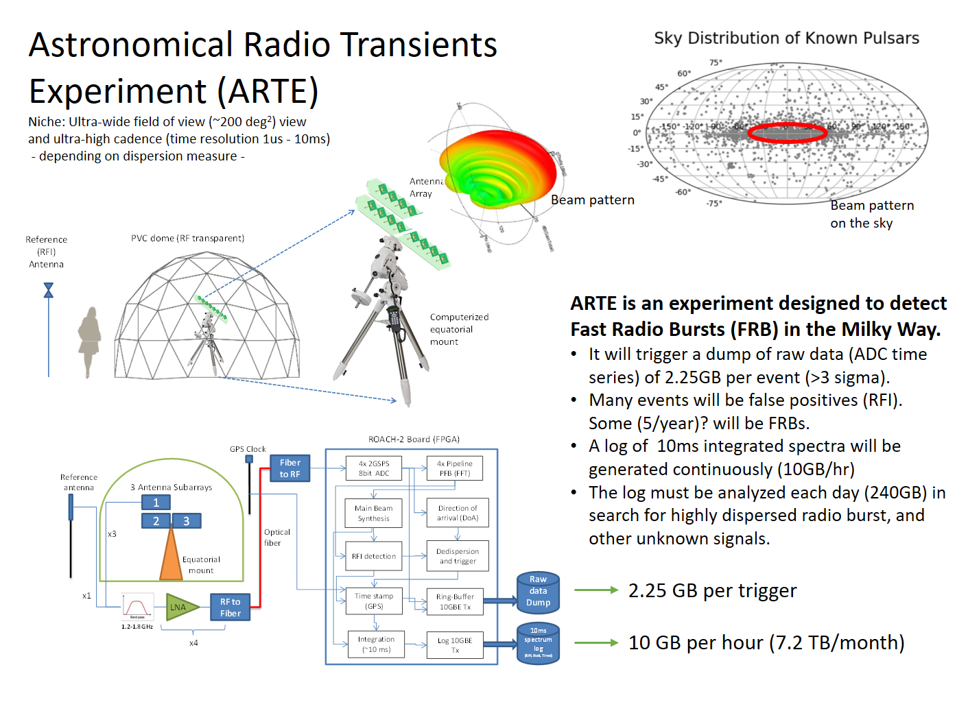
Astronomical Radio Transients Experiment (ARTE).
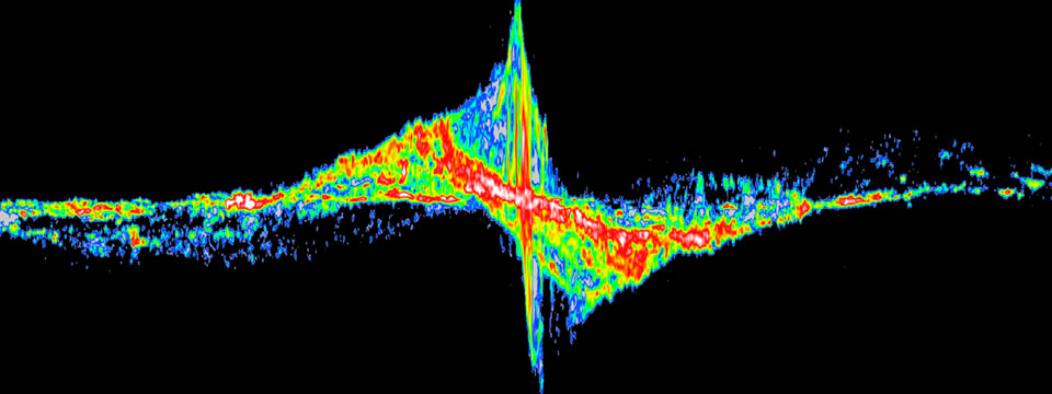
Fast Radio Bursts (FRBs,) are extraordinary astrophysical phenomena, consisting of short pulses lasting only a few milliseconds, but that may exceed the power of 500 million suns. While their nature is largely unknown they seem to be frequent, with all-sky rates estimates ranging from hundreds to thousands detectable events per day.
The history of Gamma Ray Bursts (GRB) suggests that there may be a class of radio bursts which are not as luminous as FRBs but have a much higher volumetric rate. Furthermore, an FRB occurring in the Milky Way would be an extremely bright event, detectable with small antennas. The STARE-2 experiment has been observing for more than 400 days in search for FRBs in the Milky Way. It detected many solar bursts, and one FRB associated with the known galactic magnetar SGR 1935+2154 [2020].
We aim to design and operate an improved version of the STARE-2 experiment by implementing an antenna array with a beam pattern matching the Milky Way angular distribution, therefore improving sensitivity for galactic sources while reducing Radio Frequency Interference (RFI). We also plan to triple STARE-2 bandwidth from 188 MHz to ~600 MHz, implement digital Direction of Arrival (DoA) finding, and Radio Frequency Interference (RFI) mitigation techniques.
|
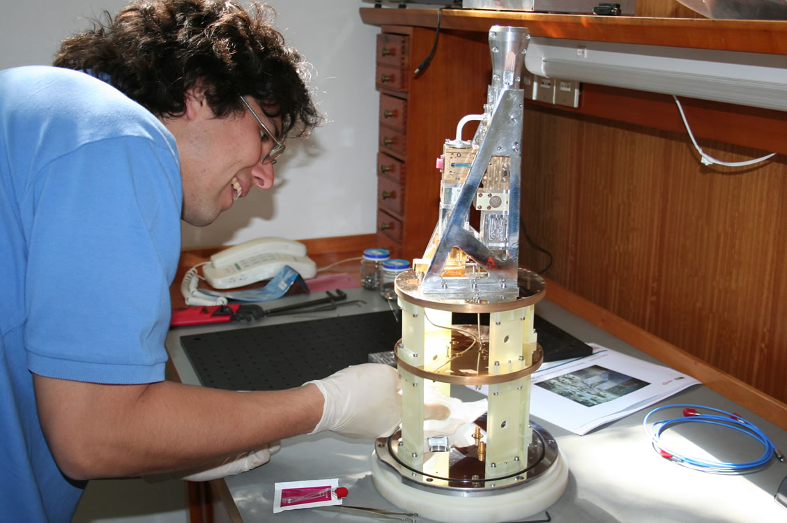
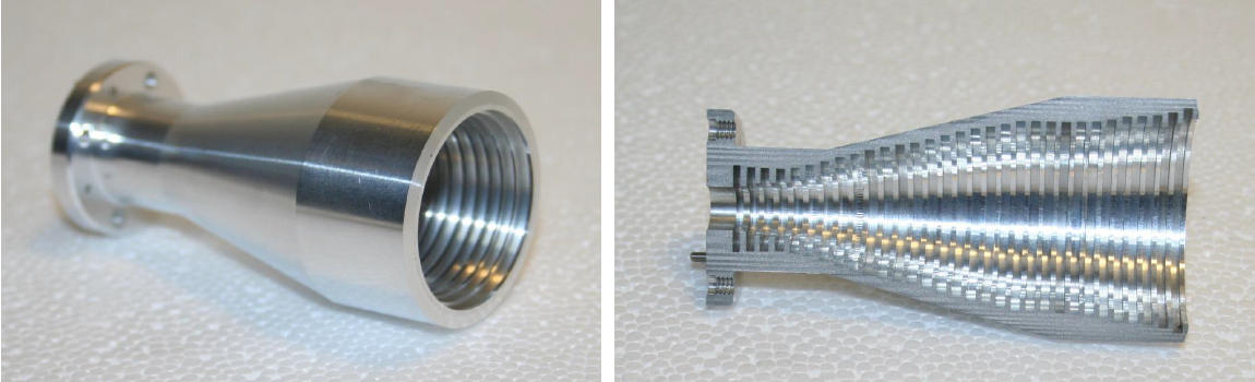
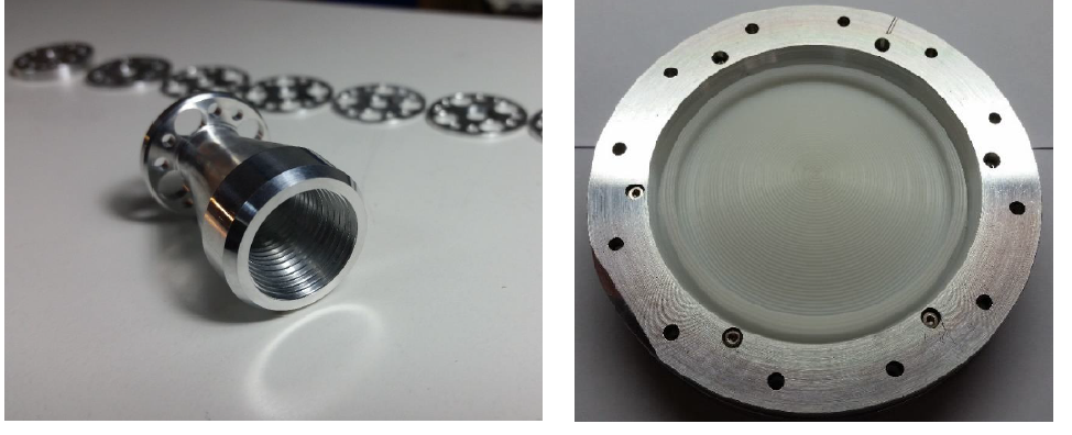
ALMA Band 1 optical system production.
The Atacama Large Millimeter Array, ALMA, is the largest radio astronomical array ever constructed. Every one of its antennas will cover the spectroscopic window allowed by the atmospheric transmission at the construction site with ten different bands. The Millimeter-wave Laboratory is running a program for the construction of the optical system (horn antenna, lens and corresponding alignment system) for band 1 of ALMA. After the designs approval by ALMA, several lenses and horns have been manufactured showing tolerances better than +/- 20 microns. First production cartridges are planned to start being delivered to ALMA after the Manufacturing Readiness Review to be held in 2017.
 |
Band 1 Horn Manufactered at the MWL | |||||
|
||||||
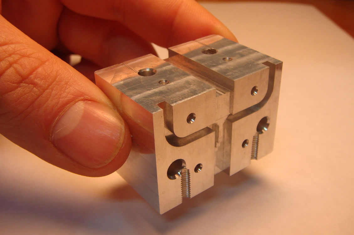
Optics for the new Band 2+3 (67-116 GHz) of ALMA.
Although ALMA, the largest radio astronomical facility ever constructed, has just started operation, a key of its long-term success will be to maintain a continuous upgrading program. The three organizations leading the project have already made calls of proposals to determine the new instrumentation that ALMA will host in the next 10 years. The Millimeter-wave Laboratory (MWL) is part of an international consortium including ESO, U. of Manchester, RAL (UK), INAF (Italy), and NAOJ (Japan), to design a prototype receiver covering the ultra-broad frequency range of ALMA Band 2+3 (67-116 GHz). Technology based on low-noise semiconductors amplifiers that will replace the superconducting mixers currently operating in ALMA. During the phase A of the project the WML has produced an optical system able to cover the entire Band. Now on phase B, the components produced in our lab are being integrated into the prototype receiver cartridge at INAF in Italy. Results will be used to propose a system upgrade to the ALMA development program.
 |
Horn and Lens Fabricated at MWL | |||||
|
||||||
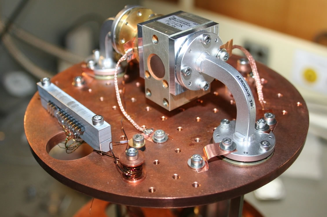
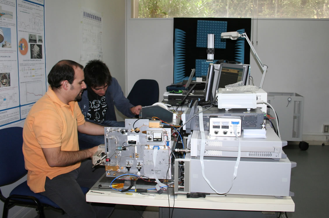
FPGA-based digital signal processing for radio astronomy
Field Programmable Gate Arrays (FPGA) are a novel way to process astronomical signals, improving performance of radio astronomy receivers beyond state-of-the-art. FPGA technology has also a wide range of applications to other areas of engineering. In the Millimeter-wave Laboratory (MWL), the area of digital back-ends has been very active both in generating new data with our home-built digital sideband separating receivers, and in developing a digital polarization receiver. Digital sideband separation on a fully assembled receiver for ALMA Band 9 (without removing the IF hybrid) was achieved on mid-2016, showing that this technique could be applied to already operative 2SB receivers without front-end modifications with a digitally calibrated receiver exhibiting cross-polarization performance 10 to 15 dB better than their purely-analog counterpart. The MWL is part of a new initiative called “ALMA Digital Front-End: Configurations Study” that aims to establish a working group which will specifically consist of front-end, back-end and system experts from major ALMA partners and JAO who will consider advanced front-end/back-end configurations.
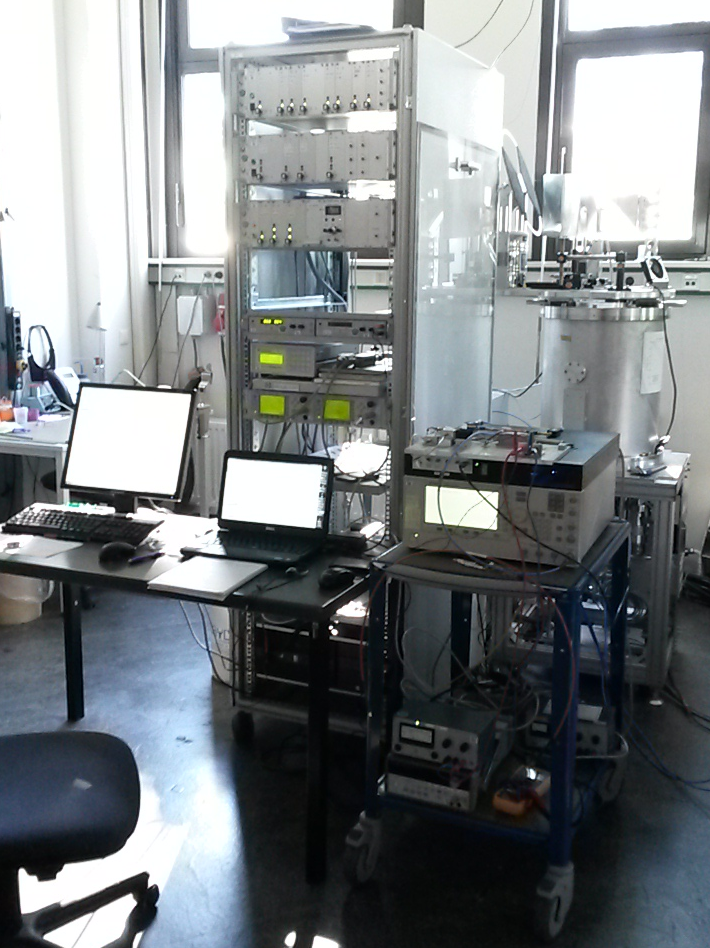 |
ALMA Band 9 Receiver With FPGA Integration . |
Receivers development for the LLAMA Radio Telescope
The Large Latin American Millimeter Array (LLAMA) Collaboration is an Argentina-Brazil project to build and operate a 12-m sub-millimeter telescope near Salta, Argentina. LLAMA will operate in single dish and VLBI modes. LLAMA is interested in the Millimeter-wave laboratory (MWL) to develop a Band 1 (35-50 GHz) and a Band 2+3 (67–116 GHz) ALMA type receivers. Using our expertise in Q and W band (30-50 GHz and 75-115 GHZ) we are developing receiver systems for these frequency ranges. For Band 2+3 we propose a receiver based on a compact I-Q sub-harmonic mixer and MMIC amplifier, obtained from CalTech. Other components, such as horns and OMTs, will use technology developed in the MWL for ALMA Band 2+3. For Band 1 we plan to use commercial amplifiers from Low Noise Factory. Other components are available from our ALMA Band 1 effort. In parallel we keep our development program on low noise amplifier design and characterization in order to be able to provide this technology as well in the future.
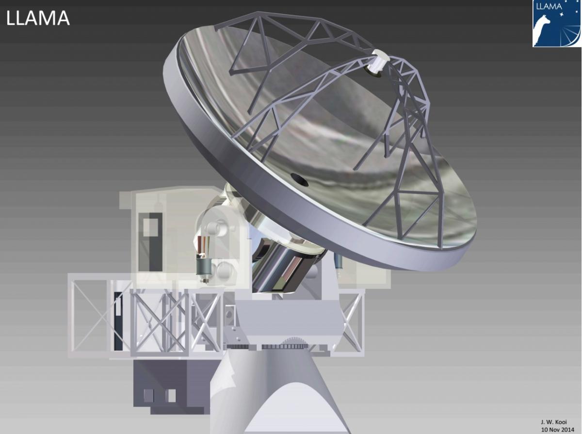 |
Future Radio-Telescope Llama. |
ALMA Band 9 sideband separation, and dual-frequency operation of Bands 6 and 9.
The Millimeter-wave Laboratory (MWL) is collaborating with SRON (The Netherlands) to improve the performance of sideband-separating receivers above 600 GHz. The MWL started providing SRON with several micro-machined components that were used for testing and as parts of functional receivers. More recently the MWL is studying the potential for performing dual observations combining Bands 6 and 9 of ALMA. The study will allow to (i) perform multi-frequency solar studies that are not hindered by the lag that exists when receivers at different frequency bands are used and (ii) accurate atmospheric calibration for Band 9 in long baselines. This time the MWL is implementing an optical system that will allow such measurements.
 |
Optical System for Mixing ALMA 6 and 9 Bands | |||||
|
||||||
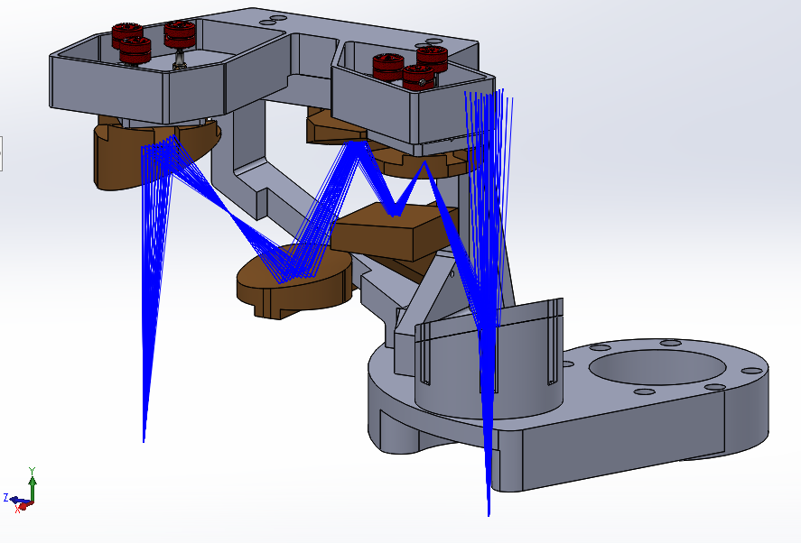
Cameras in the millimeter range
In recent years laboratories worldwide are focusing their efforts on developing heterodyne cameras in different frequency ranges. The main reason is that array instruments can increase dramatically the mapping efficiency of current telescopes. The Millimeter-wave Laboratory (MWL) have focused its work on W-band heterodyne receivers covering three areas of study:
(a) Development of optical systems for cameras: The design is intended for a 12-m class antenna, because an important potential interest of this study is the use of multi-pixel receivers in ALMA antennas. Therefore we designed a circular array of receivers with 7 pixels (extensible to 19 pixels) that fits into an ALMA style receiver cartridge.
(b) Compact feeds and orthomode transducers: This work relays on the developments associated with the ALMA Band 2+3 project. For the feed, we use smooth-wall horns to allow a compact array that fits in the available space. The possibility of using planar antennas is also considered. To take full advantage of the capabilities of a focal plane array, a double polarization scheme is desirable, so the MWL designed circular horns and OMTs to separate the two polarizations.
(c) Active components for W-Band: The MWL is developing sub-harmonic mixers based on Schottky diodes to be used as down-converters in this system, as well as power amplifiers at 60 GHz based on MMIC technology. This amplifiers are envisioned as key component of the LO routing scheme of a W-band array.
 |
Mixers Schematic for Multipixel Cameras. |
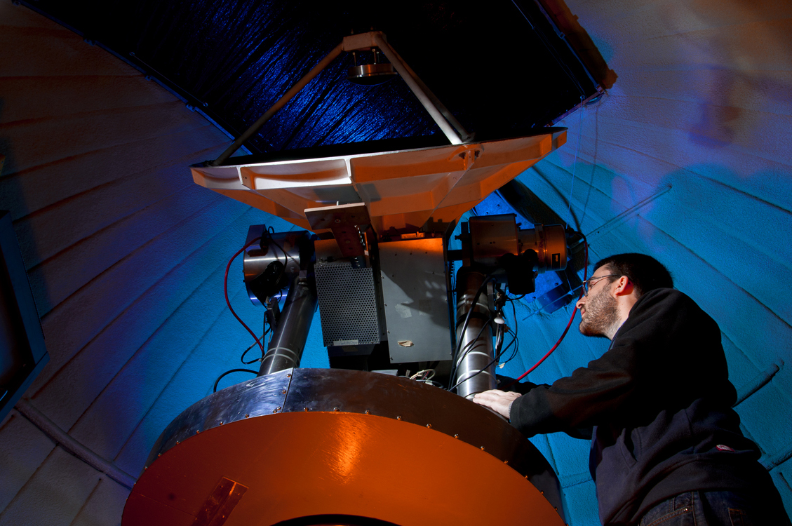
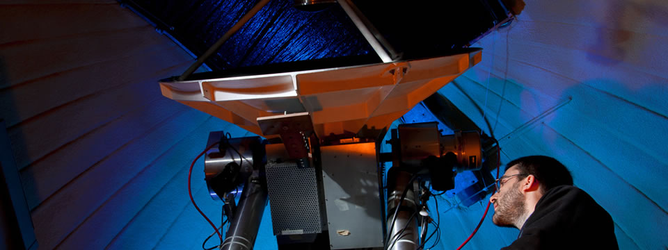
MINI Radio Telescope
The 1.2 m wave telescope (Mini) is now equipped with an innovative digital sideband-separating (2SB) receiver. Which achieves a sideband-separating ratio between 30 and 35 dB in a 500 MHz bandwidth, providing a more sensitive instrument (2015). During 2016 the telescope's control system hardware and software were modified and optimized to integrate the new digital receiver. The telescope is used for teaching at undergraduate level and to train young observational astronomers. Engineering work on the control electronics and plans for a future update of the cryogenic system are ongoing.
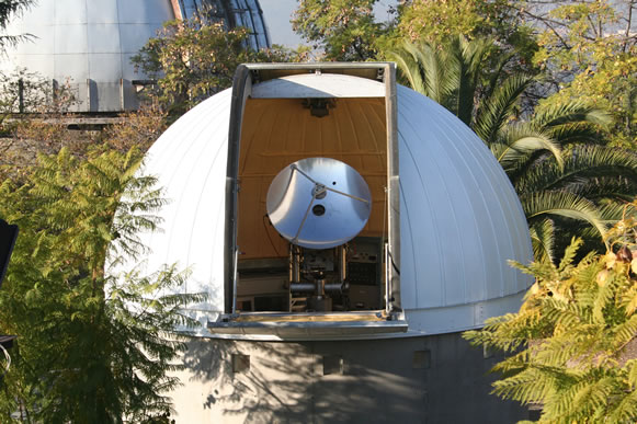 |
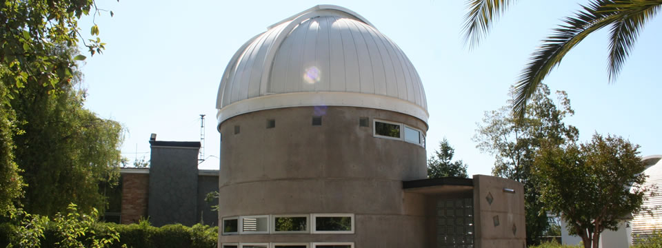
MINI radio-telescope installed in Cerro Calan in 2010. |
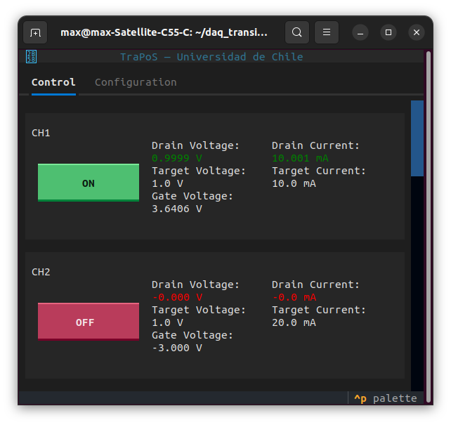
TraPoS (Transistor Power Supply)
TraPoS (Transistor Power Supply) is a programmable 8-channel power supply for FET based low noise amplifiers, which controls the drain voltage of a transistor, while maintaining a target drain current flowing through it, letting the transistor stay at its ideal operating voltage and current condition. This is accomplished by controlling the transistor’s gate voltage while measuring its drain current, and compensating the voltage drop at the drain. This device’s components allow a sufficient amount of output drain current for most, if not all, of the currently available Low Noise Amplifiers.
 |
Innovation and technology transfer
The Millimeter-wave Laboratory (MWL) also works on three non-astronomical related projects as an effort to transfer its technologies to the Chilean industry:
Telemetría para Pilas y Relaves
TPR está basado en sensores con forma de estacas que miden la humedad, temperatura, y vector de gravedad, entre otras variables del terreno. Estos datos pueden ser usadas para monitorear y controlar el riego y humedad de pilas y relaves, así como disparar alarmas en caso de movimientos inesperados o cambios en la inclinación del terreno. Cada estaca reporta la información de forma inalámbrica a una central que puede estar a varios kilómetros de la pila o tranque. Esta información es guardada en una base de datos y desplegada de manera gráfica en cualquier navegador web.
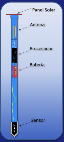 |
TPR is a monitoring system for measuring humidity, temperature and mechanical stability of leaching heaps, mining tailings and other applications | |||||
|
||||||
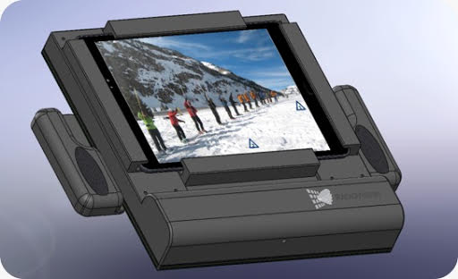
Radio Vision
A novel device for cell phone detection is been developed in the CATA/DAS laboratory. The detector is based in phased array antenna technology which is primary used in radio astronomy applications. The device will allow location of cell phones’ emissions on a 60x60 deg field of view. The commercial applications of this device varies from locating people trapped under snow avalanches or collapsed buildings to cell phone detection in prisons, airplanes or other places where phones are not allowed. The development of the first prototype is well under way and is composed of an antenna array, a beam forming circuitry based on commercially available parts, and an embedded computer for control and display. This project won prize at the nation-wide innovation contest OpenBeauchef.
 |
Portable phased array for cellular phone detection | |||||
|
||||||
Wood Moisture Content.
The MWL is developing a device to measure the moisture content of wood using microwave absorption in collaboration with a Chilean technology company. So far experiments show good results measuring individual wood planks but some inconsistencies for plank banks. We are currently exploring a new frequency band, and new antenna designs to provide the required accuracy in less controlled environments. This device has applications in the forest (cellulose) industry and to enforce firewood moisture content regulations, among others.
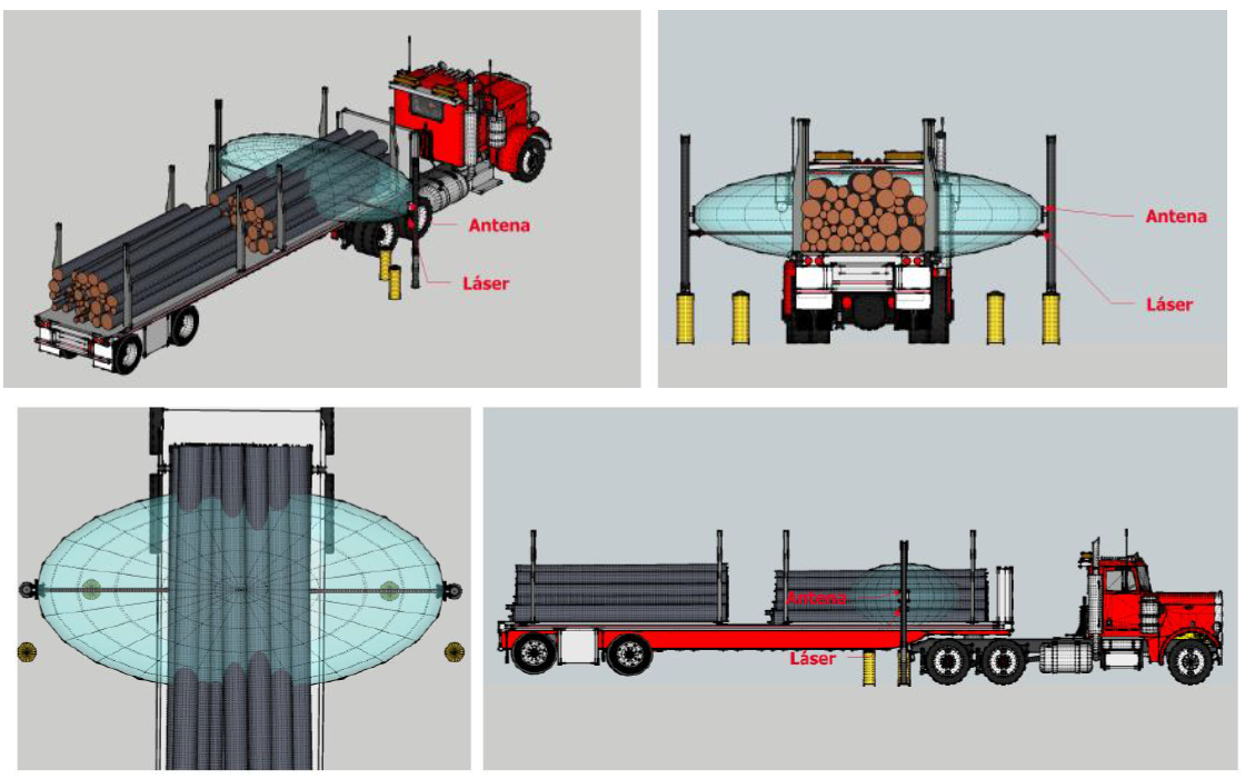 |
Microwave Wood Moisture System |
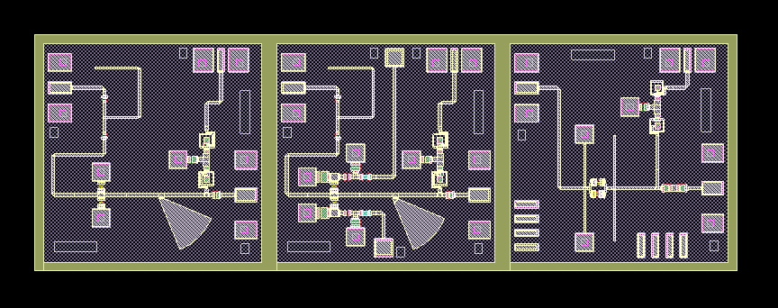
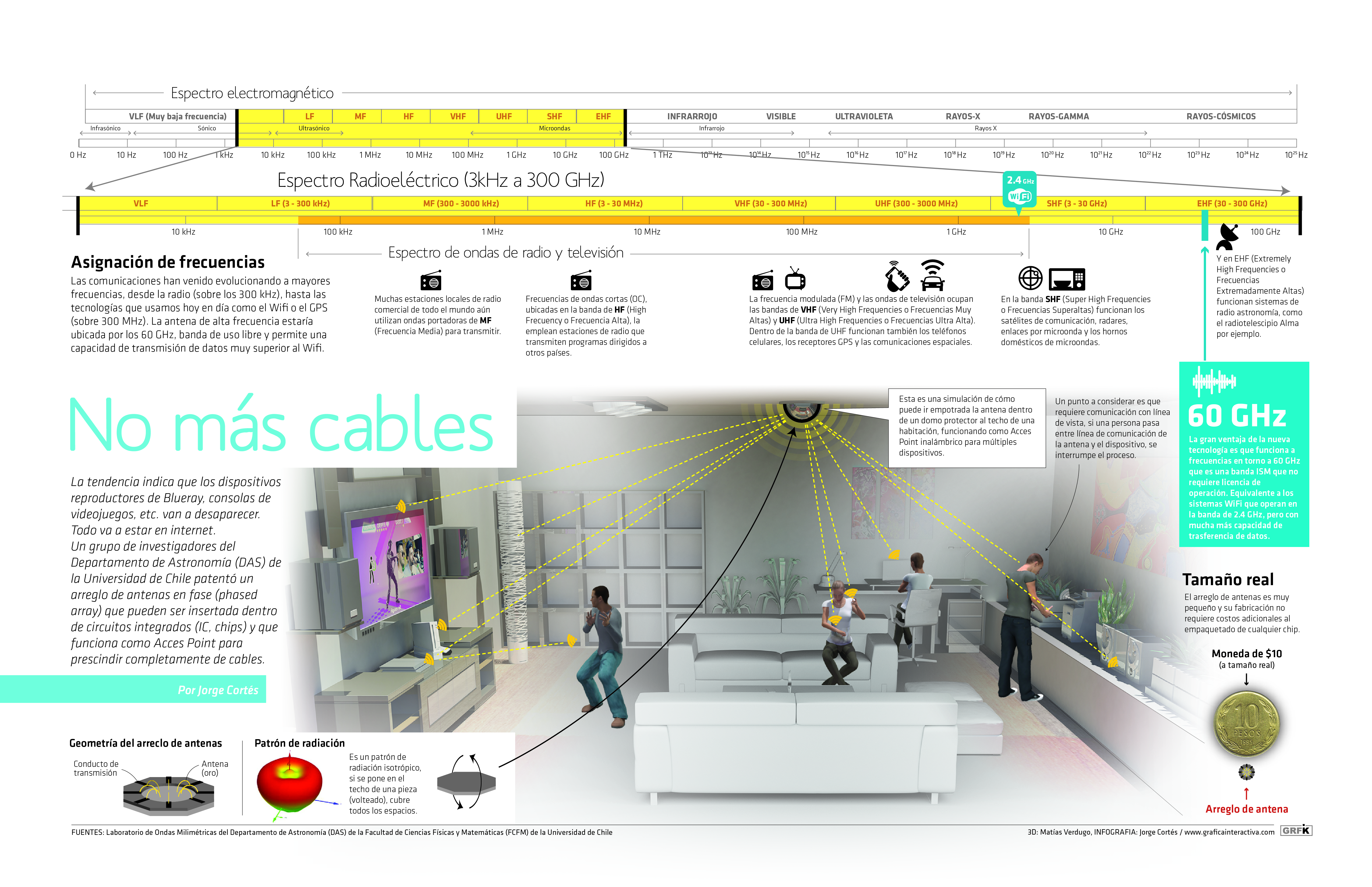
Circular Bond-Wire Array Antenna
In the pursuit of higher data transfer rates for short range wireless communication purposes such as Wi-Fi and point-to-point networks, the 60 GHz ISM band is expected to gain popularity in the near future. This is leading to new antenna designs that can be fully integrated with the front-end electronics. The main two types of integrated antennas are the Antenna on Chip (AoC) and the Antenna in Package (AiP). A third, hybrid, antenna model is the Bond-Wire Antenna (BWA), which combines a relatively high radiation efficiency with excellent integration possibilities. This project proposed an array antenna design that can achieve such a radiation pattern. A prototype of the BWA array was constructed and tested at the laboratory showing good performance. A circular array of BWA elements can provide a broad and omnidirectional pattern, with each BWA being very directive. This makes it excellent for point to point applications, where transmitter and receiver positions are fixed. A new iteration of this antenna is under development to address construction difficulties and improve efficiency. The technology transfer scope for this is worldwide as there are no hardware factories in Chile that package microchips.
 Point-to-point
60 GHz BWA network aplication concept Point-to-point
60 GHz BWA network aplication concept |
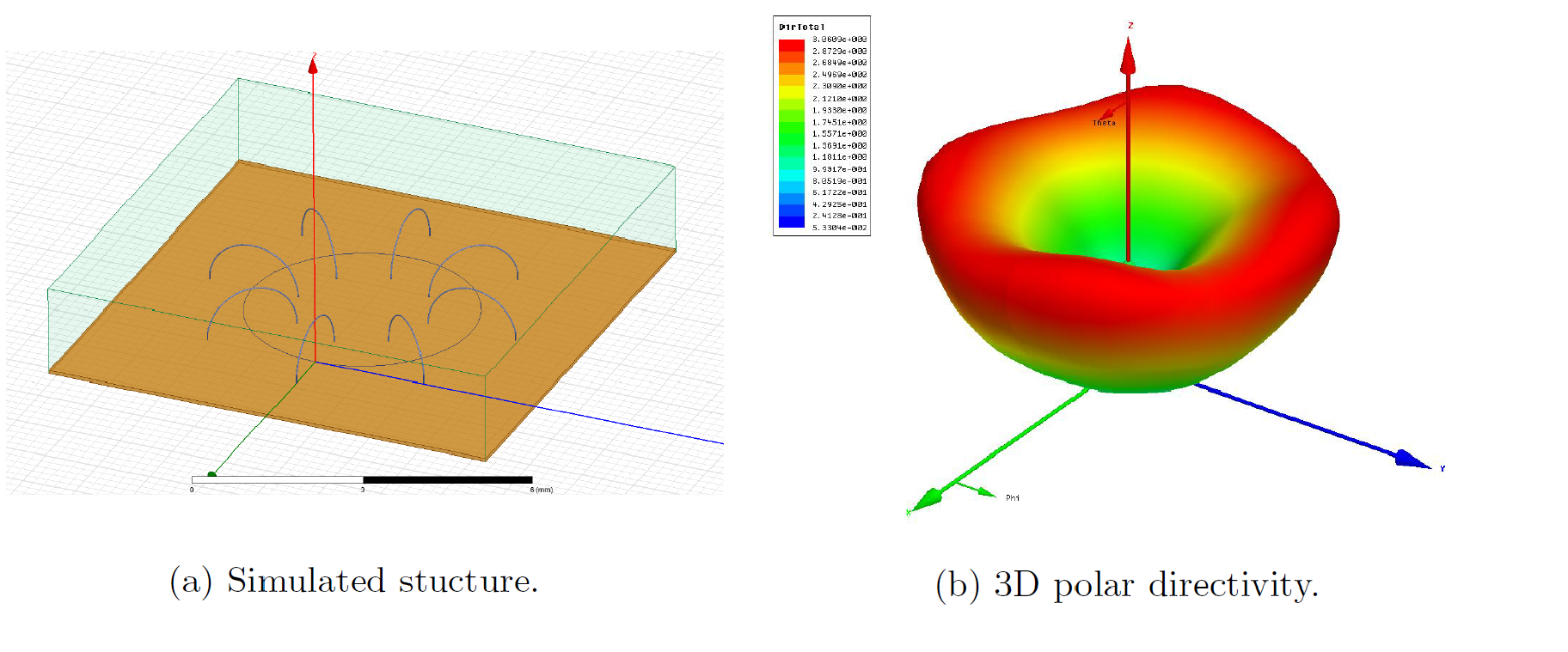 BWA array design (a). Antenna directivity (b) |